LTE-Advanced and the Evolution to 4G Cellular Systems

Project Description

Service Architecture Evolution (SAE) & Long Term Evolution (LTE)

The Third Generation Partnership Project (3GPP) specifies in its 3GPP Release 8 the elements and requirements of the Evolved Packet System (EPS) architecture that will serve as basis for next-generation networks. The most important work items in 3GPP Release 8 are the service architecture evolution (SAE) and long term evolution (LTE), which led to the specifications of the Evolved Packet Core (EPC), Evolved Universal Terrestrial Radio Access Network (E-UTRAN) and Evolved Universal Terrestrial Radio Access (E-UTRA)


EPC Overview

The EPC is a flat all-IP-based core network that can be accessed through 3GPP radio access (LTE, 3G, 2G) and non-3GPP radio access (e.g. WiMAX, WLAN), allowing handover procedures within and between both radio access types. The access flexibility to the EPC is attractive for operators since it enables them to have a single core network through which different services are supported. The main components of the EPC are the following:

  • Mobility Management Entity
  • It is a key control element. It is in charge of managing security functions (authentication, authorization, Network Access Server (NAS) signaling security), idle state mobility handling, roaming and handovers among other functions. The S1-MME interface connects the EPC with the evolved Node Bs (eNBs, base stations in LTE).

  • Serving Gateway (S-GW)
  • It is the gateway that terminates the EPC interface towards the E-UTRAN via an interface called the S1-U. For each UE that is associated with the EPS there will be a unique S-GW hosting several functions. Mobility anchor point for both local inter-evolved Node Bs (eNB) handover and inter-3GPP mobility, inter-operator charging and packet routing and forwarding are some of them.

  • Packet Data Network Gateway (PDN-GW)
  • It provides the user equipment (UE) with access to a packet data network (PDN) by assigning an IP address from the PDN to the UE among other functions. Additionally, the Evolved Packet Data Gateway (ePDG) provides security connection between an UE connected from an untrusted non-3GPP access network with the EPC by using IPSec tunnels.

However, from a user-plane perspective, there are only the base station (eNodeB) and the gateways, which is why the system is considered “flat”. This results in a reduced complexity compared to previous architectures. For further details regarding these elements and other elements of the EPC, the official specifications can be found in [1] and [2].


LTE E-UTRAN Overview

The E-UTRAN architecture consists of eNBs that provide the air interface user plane and control plane protocol terminations towards the UE. On one side, the user plane protocols consist of Packet Data Control Plane (PDCP), Radio Link Control (RLC), Medium Access Control (MAC) and Physical Layer (PHY) protocols. On the other side, the control plane protocol refers to the Radio Resource Control (RRC) protocol.

Each of the eNBs are logical network components that serve one or several E-UTRAN cells and are interconnected by the X2 interface. Additionally, Home eNBs (also called femtocells), which are eNBs of lower cost, can be connected to the EPC directly or via a gateway that provides additional support for a large number of HeNBs

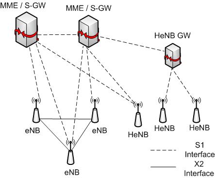
E-UTRAN architecture.

The main functionalities hosted by the E-UTRAN are enumerated in the following:

  • Inter-cell Radio Resource Management (RRM)
  • Resource Block control
  • Connection mobility control
  • Radio admission control
  • eNB measurement configuration and provisioning
  • Dynamic resource allocation (scheduling)

LTE Air Interface Overview

The LTE E-UTRA work item is essential so that an optimized packet-based access system can achieve the expected system performance in terms of high data rates and low latency. E-UTRA is also expected to support mobility up to 350 km/h, conserve mobile station’s power consumption through micro-sleep, and provide seamless integration of unicast and enhanced broadcast transmission. Key techniques for the LTE air interface are summarized as follows:

  • Orthogonal Frequency Division Multiplexing Access (OFDMA) for the Downlink
  • OFDMA allows data to be transmitted in parallel in a set of narrowband, orthogonal, and tightly close sub-carriers, providing an efficient use of the available bandwidth. The use of cyclic prefix in OFDMA makes it robust to time-dispersion (multipath) without the need of complex equalizers in the receiver end, which reduces complexity, cost and power consumption.

  • Single-Carrier Frequency Division Multiple Access for Uplink
  • One of the disadvantages of OFDMA is that it produces large output variations, which require highly linear power amplifiers that are inherently low power efficient. Since power consumption is extremely important for the UE, plain OFDMA is not used for the uplink but a DFT-precoded OFDM, also known as Single-Carrier OFDMA (SC-FDMA). SC-FDMA comes as a power efficient alternative of OFDMA that keeps most of the advantages of OFDMA.

  • Multiple-Input Multiple-Output (MIMO) transmission
  • MIMO techniques enhance system performance, service capabilities, or both. At its highest level, LTE multi-antenna transmission can be divided into transmit diversity and spatial multiplexing. The former can can be seen as a technique for averaging the signals received from the two antennas, thereby avoiding the deep fading dips that occur per antenna. The latter employs multiple antennas at the transmitter and receiver side to provide simultaneous transmission of multiple parallel data streams over a single radio link, therefore increasing significantly the peak data rates over the radio link. Additionally, LTE supports SDMA (Spatial Division Multiple Access) and beamforming.

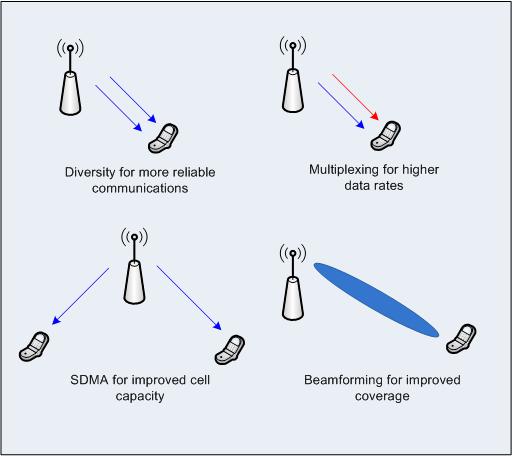
    MIMO techniques in LTE.

  • Channel-dependent scheduling
  • A common property of the radio channel is its variation in both frequency and time. Instead of trying to fight against and overcome these channel variations, LTE advocates to utilize these channel variations as input to the scheduler. In other words, by taking into account the channel conditions at each time and frequency block (called radio resource block or RRB), the scheduler can select the users that experience the best channel condition in each RRB, achieving the maximum possible performance. In order to perform this scheduling, the scheduler requires feedback from the UEs regarding the channel state that they are experiencing.

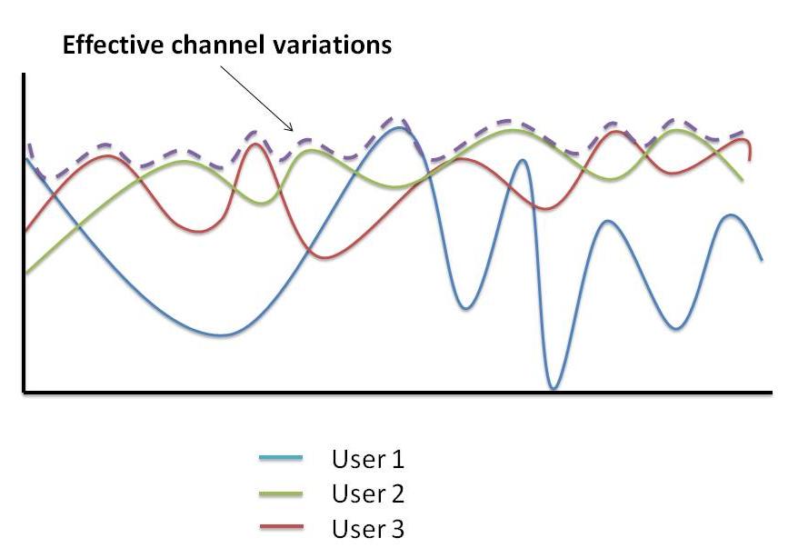
    Channel-dependent scheduling.

  • Retransmission scheme
  • In order to handle transmission/reception errors, LTE uses a combination of selective-repeat ARQ and hybrid-ARQ. In this way it can rapidly recover from errors through the hybrid-ARQ maintaining a low feedback overhead, while at the same time having a robust fallback recovery method (ARQ) when hybrid-ARQ is not enough to recover from the error. In this way, a combination of low overhead/latency from hybrid-ARQ (which will manage most of the errors) and high reliability from ARQ is obtained.

  • Spectrum flexibility
  • LTE provides a single radio interface supporting both FDD and TDD. Most of the processing for TDD and FDD is the same, except for the frame structure. This allows easier and lower cost implementation of devices that support both TDD and FDD. In addition, to provide great operational flexibility, E-UTRA physical layer specifications are bandwidth agnostic and designed to accommodate up to 20 MHz system bandwidth. The following table shows the downlink parameters for the different bandwidth allocations.


    Transmission Bandwidth (MHz) 1.4 3 5 10 15 20
    Subframe duration 1 ms
    Sub-carrier spacing 15 kHz
    Sampling frequency (MHz) 1.92 3.84 7.68 15.36 23.04 30.72
    FFT Size 128 256 512 1024 1536 2048
    Number of occupied sub-carriers 75 150 300 600 900 1200
    Cyclic Prefix Length (μs) Short CP 4.69x6   5.21x1
    Long CP 16.67


  • Inter-cell interference coordination
  • Since UEs utilize OFDMA and SC-FDMA for downlink and uplink, respectively, their transmission are orthogonal and should not interfere with each other within a cell (intra-cell interference). However, since LTE advocates for full frequency reuse, a UE could receive interference from other UEs that have been assigned the same RB in a different cell. This problem will affect the most to the UEs that are located at the cell-edge since they will be farther away from the base station of the cell that they belong and nearer to the UEs and base station in a neighbor cell. To reduce this interference, LTE allows coordination between different base stations so that they can identify which UEs are located near the cell-edge and dynamically assign preferably complementary parts of the spectrum to reduce the inter-cell interference. Inter-cell interference coordination techniques are applied both for uplink and downlink.

[Back to top]

LTE-Advanced: Requirements

3GPP decided to further enhanced LTE not only to qualify as a 4G technology but to surpass it. In order to do so, it defined the following requirements:

  1. Increased peak data rates (Gbit/s):

    Low mobility scenario High mobility scenario
    1 0.1

    Downlink Uplink
    1 0.5
  2. Improved cell edge throughput

    Antenna Configuration [bps/Hz/cell/user]
    UL 1x2 0.04
    2x4 0.07
    DL 2x2 0.07
    4x2 0.09
    4x4 0.12
  3. Improved spectrum efficiency:
    • Peak (bps/Hz)

      Downlink Uplink
      1 0.5
    • Average

      Antenna  Configuration [bps/Hz/cell]
      UL 1x2 1.2
      2x4 2.0
      DL 2x2 2x4
      4x2 2.6
      4x4 3.7
  4. Spectrum flexibility:
    • New spectrum bands are available (in addition to those of Release 8):

      Bands (MHz) Bands (GHz)
      450-470 2.3-2.4
      698−862 3.4-4.2
      790−862 4.4-4.99

    • In addition to the bandwidths of Release 8, LTE-A should support wider bandwidths allocations of up to 100 MHz, possible aggregating contiguous and/or noncontiguous spectrum. Also, it should support both unpaired (TDD) and paired (FDD) spectrum allocations
  5. Interworking: Should provide better, or at least the same, performance of Release 8
  6. Mobility:

    Speed (km/h) Support
    0-10 Enhanced
    10 – 350 Preferably enhanced (at least not worst than LTE)

In addition to the previous requirements, LTE-A is targeted to have low cost and complexity UE and infraestructure, enhanced support for MBMS and VoIP, and considers deployment scenarios for indoor eNodeBs. For more detailed information regarding each of these requirements, the official specifications can be found at [X1] and [X2]

[Back to top]

LTE-Advanced: Technical Proposals

In order to fulfill these requirements, LTE-A propose the following techniques:

  1. Carrier Aggregation:

    While in LTE the maximum bandwidth considered was 20 MHz. LTE-A will support up to 100 MHz bandwidth by aggregating two or more LTE "Component Carriers" (CC) of up to 20MHz. These component carriers can be continuous or discontinuous in a single spectrum band, or from different spectrum bands.

  2. Enhanced MIMO

    Multi-antenna techniques are already one of LTE key features and are expected to have even a greater importance in LTE-A systems. In order to meet the peak spectrum efficiency, antenna configurations of 8x8 for downlink transmission and 4x4 for uplink transmission are being investigated. Further, LTE-A MIMO technologies are also designed with the aim of improving cell average throughput as well as cell edge performance. An uniform and adaptive MIMO platform is thought in order to accomodate demand of high data rates and wider coverage by switching from one mode to another. Two main approaches are distinguished in LTE-A MIMO: single-site MIMO, where only one base station is utilized for the transmission and multi-site MIMO where several base stations may collaborate in the transmission of a single stream

  3. Coordinated multiple point (CoMP) transmission and reception:

    LTE-A defines in general terms CoMP as the "coordination in the downlink/uplink from/to multiple geographically separated transmission/reception points". Antennas of multiple cell sites are used in such a way that they can contribute to improve the quality of the received signal at the UE/eNB and drastically reduce the inter-cell interference. This will demand very fast inter-eNB connections and some additional control strategy that might be centralized or not. 

  4. Relaying: In order to improve coverage of high data rates, group mobility, temporary network deployment, cell-edge throughput, and to provide coverage in new areas, LTE-A includes support for relays. The basic architecture analyzed for LTE-A consists of a single relay node (RN) that is connected to a donor cell of a donor eNodeB.

Beyond these technical proposals already identified by 3GPP to improve the overall performance of the network, there are several other technologies and techniques that can be incorporated into next generation cellular systems to improve their performance. We will explore several of these options and their applicability to next generation cellular systems.


[Back to top]

You are visitor:

since 11/13/2009.